Every steel building stands only as strong as the foundation beneath it. In Ontario, where soil conditions, frost depth, and building codes demand strict precision, engineered foundation drawings are not optional – they are essential.
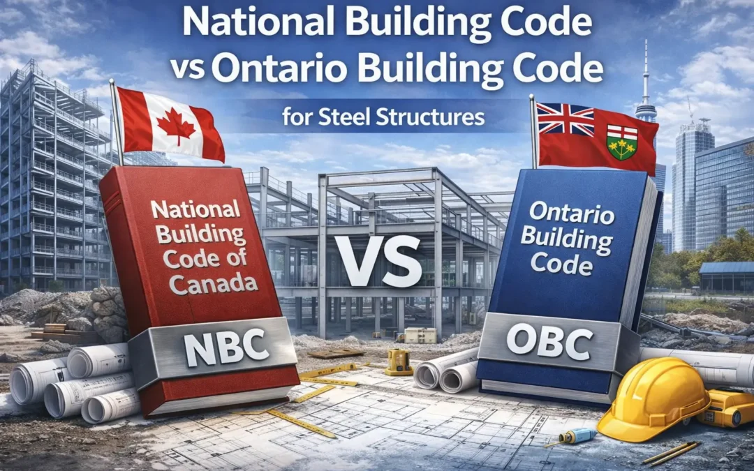
These drawings form the backbone of every successful project, translating engineering data into actionable construction details. They define how loads transfer from the steel structure into the ground, ensure compliance with the Ontario Building Code (OBC), and provide the information required for both permits and on-site construction.
This guide explains what steel foundation drawings in Ontario include, why they matter, and how Tower Steel Buildings ensures every client receives certified, engineer-stamped documentation ready for permit and construction approval.
Understanding the Role of Engineered Foundation Drawings
Foundation drawings are a core part of the construction documentation package for any pre-engineered or custom steel building. They serve three primary functions:
- Engineering Validation – confirming that the design meets Ontario’s soil and structural load conditions.
- Construction Blueprint – providing contractors and concrete crews with exact placement and rebar specifications.
- Permit Compliance – ensuring municipal reviewers can verify that the design aligns with local regulations and the Ontario Building Code.
Without these documents, no steel structure can safely or legally move forward in Ontario.
What’s Included in a Steel Foundation Drawing Package
A typical engineered steel building foundation drawing package prepared by Tower Steel Buildings includes a complete set of structural blueprints and details stamped by a licensed Ontario Professional Engineer (P.Eng.).
Below are the key components included in every foundation drawing set:
A. Foundation Plan
The foundation plan provides a top-down layout of the entire concrete system, illustrating the position of:
- Anchor bolt locations
- Footings and pads
- Column piers
- Grade beams and perimeter walls
- Slab thickness and rebar grid patterns
Every line, symbol, and dimension ensures accurate placement and alignment with the steel superstructure that will be erected later.
B. Anchor Bolt Layout
Anchor bolts are among the most critical elements in connecting steel columns to the foundation. Their layout drawing specifies:
- Bolt size, length, and grade
- Spacing and bolt circle dimensions
- Template placement coordinates
- Grout and embedment depths
Even minor deviations can lead to structural misalignment. Tower Steel’s engineering team provides anchor bolt templates and placement drawings that correspond exactly to the building’s column base plates – ensuring the steel fits perfectly during erection.
C. Load Path and Reaction Details
These drawings outline how forces from the building are transferred into the foundation. They include:
- Axial loads from columns
- Lateral loads from wind or seismic activity
- Uplift reactions due to wind loads
- Moment reactions for rigid frame bases
Ontario’s varying soil conditions make this step vital. Engineers evaluate load distribution to prevent settlement, cracking, or overturning under extreme conditions.
D. Concrete Section Details
Cross-sectional views show depth, reinforcement, and composition of each structural element.
This includes:
- Column pier dimensions
- Slab reinforcement (rebar and mesh patterns)
- Edge thickening and perimeter footings
- Concrete strength and curing specifications
Concrete design strength is typically rated in MPa (megapascals), often ranging between 25 MPa and 35 MPa for standard foundations, with adjustments based on soil bearing capacity.
E. Rebar and Reinforcement Schedule
This section defines every reinforcement bar’s size, quantity, and spacing. For example:
- #15M rebar at 300 mm spacing for grade beams
- #20M longitudinal bars in column footings
- Reinforcement hooks, laps, and ties
Each rebar schedule ensures that load transfer is balanced and cracking is minimized. It also includes concrete cover requirements to prevent corrosion – particularly important in Ontario’s freeze-thaw conditions.
F. Elevation Views
Elevation drawings provide a side view of the foundation system, showing relative heights, slab elevations, and step-down transitions. These details ensure proper drainage, accessibility, and alignment with floor elevations across the site.
G. Foundation Notes and General Specifications
This section includes all general notes required by building inspectors and contractors, such as:
- Concrete mix design and curing time
- Rebar cover minimums
- Frost protection depth (minimum 1.2 metres across most of Ontario)
- Soil bearing capacity (measured in kPa)
- Reference standards (CSA A23.3, OBC Part 4, etc.)
These details verify compliance with both Ontario engineering standards and municipal construction bylaws.
H. Stamped Engineering Certification
Every Tower Steel Buildings foundation drawing is reviewed and sealed by a licensed Professional Engineer registered in Ontario.
This certification verifies:
- Structural adequacy
- Compliance with the Ontario Building Code
- Accuracy of load assumptions and design data
Stamped drawings are required for permit submission and provide assurance for contractors, inspectors, and building owners that the structure is safe and approved for construction.
How Tower Steel Buildings Prepares Foundation Drawings
The foundation design process begins well before concrete is poured. Tower Steel Buildings integrates engineering data, soil reports, and design loads into a unified documentation process that streamlines construction and inspection.
Step 1: Load Data Collection
The engineering team begins by gathering structural load data from the building’s framing design – including:
- Dead loads (steel weight)
- Live loads (occupancy, equipment)
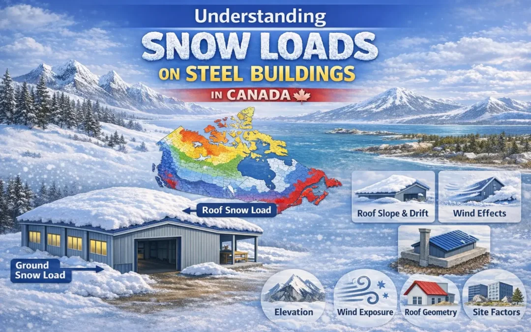
- Snow and wind loads based on Ontario location
- Seismic loads (where applicable)
These loads are translated into column reactions and used to design the footings and piers.
Step 2: Site Information and Soil Data
Ontario’s soil types vary widely – from clay and silt in the south to gravel and bedrock in the north. Tower Steel recommends a geotechnical report before design begins to determine:
- Soil bearing capacity
- Water table depth
- Frost penetration
- Compaction requirements
This ensures each footing and slab section is tailored to the specific site’s conditions.
Step 3: Foundation Design and Modeling
Using structural engineering software, designers create 2D and 3D models to analyze stress points and deflection under various load combinations.
The result is a foundation optimized for performance, cost, and constructability.
Step 4: Drafting and Detailing
All drawings are produced with CAD and Revit-based drafting tools, allowing precision alignment with steel column grids. Each file includes a detailed legend, revision schedule, and layout suitable for both digital and printed use on-site.
Step 5: Engineering Review and Stamp
The final stage includes peer review by an Ontario-licensed Professional Engineer. The drawings are stamped, signed, and issued as part of the permit-ready construction documentation.
Why Proper Foundation Drawings Matter
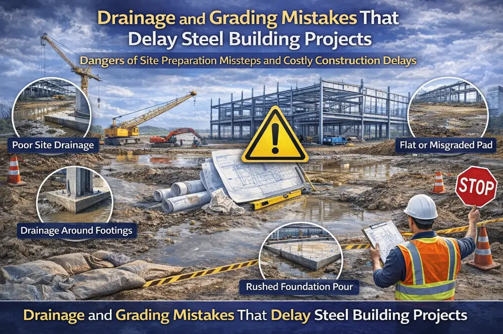
Skipping or rushing the foundation design process can lead to costly setbacks. Errors in anchor bolt placement, underdesigned footings, or incorrect rebar spacing can cause major alignment and safety issues.
Here’s why detailed, engineered drawings matter:
Accuracy During Construction
Concrete crews rely on foundation blueprints for precise placement. Any deviation can delay steel erection or require costly modifications.
Permit Approval
Municipalities across Ontario – from Toronto to Sudbury – require stamped foundation drawings as part of the permit package. Without them, construction cannot proceed legally.
Long-Term Performance
Proper footing and load path design prevent differential settlement, frost heaving, and cracking – ensuring the building’s longevity.
Coordination with Steel Fabrication
Anchor bolt layouts must align perfectly with the pre-fabricated steel structure. Tower Steel Buildings provides both sets of drawings to eliminate field errors and ensure seamless installation.
Common Foundation Types for Ontario Steel Buildings
Depending on soil and building use, Tower Steel Buildings designs several foundation systems:
- Isolated Footings: Ideal for smaller structures and light industrial buildings.
- Continuous Grade Beams: Connect multiple footings and improve load distribution.
- Thickened Edge Slabs: Used for garages or smaller workshops with integrated foundations.
- Pile or Caisson Foundations: For soft soil or high water tables, often used in northern Ontario.
Each design is selected based on soil report recommendations, load requirements, and frost protection needs.
Tower Steel Buildings – Precision and Compliance in Every Drawing
Every Tower Steel Buildings project is supported by certified, engineered drawings produced by Ontario professionals with decades of experience in structural design.
What Clients Receive
- Full foundation plan, details, and notes
- Anchor bolt templates
- Rebar and concrete specifications
- Engineering stamp and compliance certificate
- Coordination with steel frame design
By providing all design and fabrication in-house, Tower Steel ensures that foundation drawings align perfectly with the building structure, eliminating guesswork and field adjustments.
Reviewed by the Tower Steel Buildings Engineering Team
This article has been reviewed and verified by the Tower Steel Buildings Engineering Team, ensuring all information aligns with Ontario’s structural design practices and current OBC standards.